• When you click on links to various merchants on this site and make a purchase, this can result in this site earning a commission. Affiliate programs and affiliations include, but are not limited to, the eBay Partner Network.

69 Roadrunner mutt car!!

Big John

Sit back, relax Don't bitch about the cigar smoke
Joined
Sep 8, 2008
Messages
5,057
Reaction score
79
The horn relay should be under the hood, mounted by the horns. All the 68 and 69 Roadrunners are like that.

Here's the link to the FSM. You have to be logged in to see the reference section. http://www.69roadrunner.net/mopar/showthread.php?330-01-Dealer-Reference-Service-Manual

The "P and N" you mention does not work that way. The ignition switch in "start" position bypasses the ballast resistor and provides full voltage to the ignition. When the trans in in park and neutral, it returns ground to the starter relay so the starter can engage.

Oh... and it's John, not Mike.
 
Joined
Feb 19, 2016
Messages
22
Reaction score
0
Location
Texas
The horn relay should be under the hood, mounted by the horns. All the 68 and 69 Roadrunners are like that.

Here's the link to the FSM. You have to be logged in to see the reference section. http://www.69roadrunner.net/mopar/showthread.php?330-01-Dealer-Reference-Service-Manual

The "P and N" you mention does not work that way. The ignition switch in "start" position bypasses the ballast resistor and provides full voltage to the ignition. When the trans in in park and neutral, it returns ground to the starter relay so the starter can engage.

Oh... and it's John, not Mike.

My apologies for the calling you Big Mike.. My bad.

I stay logged in, so I will try again with the link. Thanks for that.

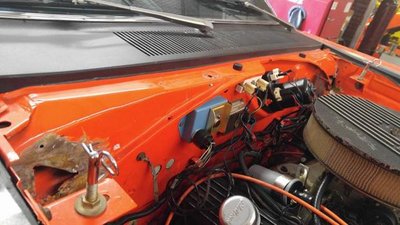
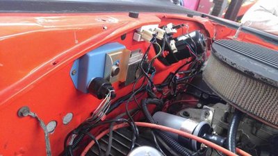
According to the test light and my handy mirror out the door over the engine bay trick (being by myself :lol: ), these two circuits showed power while the key engages the start circuit. Hum.. Ok then, which pins should I use to energize my MSD box with a keyed 12+ energized during the start sequence? I am not planning on reinstalling the factory ignition equipment. So I am planning on pinning the MSD supplied wires straight into the factory bulkhead connectors as this will give me the cleanest looking and most reliable connection.
 

Big John

Sit back, relax Don't bitch about the cigar smoke
Joined
Sep 8, 2008
Messages
5,057
Reaction score
79
We might not be talking about the same thing. When you said "P and N", I thought park and neutral. Now I realize you are talking about the P and N locations on the bulkhead connector.

I'll take a look at the bulkhead connector diagram a little later and report back.
 

Big John

Sit back, relax Don't bitch about the cigar smoke
Joined
Sep 8, 2008
Messages
5,057
Reaction score
79
I have cavity "Q" (next to "P"), brown wire, that hooks to ignition 2. That would be 12 volt+ to the ignition when you are starting the car.

Cavity "T" is for the starter. Yellow wire. That will feed the starter relay.

Cavity "N" is ignition 1. Dark Blue wire. 12v + to the ballast resistor when the key is on and the engine running.
 

Big John

Sit back, relax Don't bitch about the cigar smoke
Joined
Sep 8, 2008
Messages
5,057
Reaction score
79
I hooked up my MSD with the 12 volt feed from the starter relay to power it.

I bypassed the ballast resistor and used the ignition 1 and 2 to trigger the MSD on and off.
 
Joined
Feb 19, 2016
Messages
22
Reaction score
0
Location
Texas
OK thanks again for the service manual. That thing takes a minute to get through but I will. Thanks again.
 
Joined
Feb 19, 2016
Messages
22
Reaction score
0
Location
Texas
Ok so when you are referring to "ignition 1" and "ignition 2" are you referring to the N and P circuits from the bulk head Or are you referring to Q and N or something different all together? My apologies for my ignorance here, I just can't find any reference to "ignition 1 or 2".

Here is how I am interpreting this

PIN Q = Ign 1 (to energize MSD 12+ while in start circuit)
PIN N = Ign 2 (to maintain 12+ after start circuit is released) These two circuits are connected together in order to make this one circuit? That allows the MSD to stop receiving signal when key is shut off.
 
Last edited:
Joined
Feb 19, 2016
Messages
22
Reaction score
0
Location
Texas
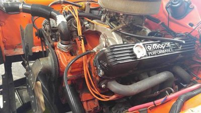
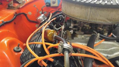
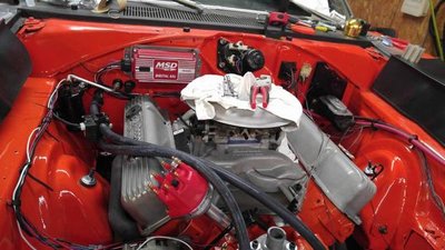
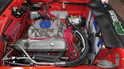
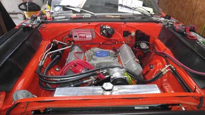
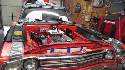
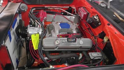
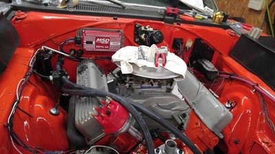
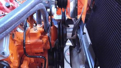
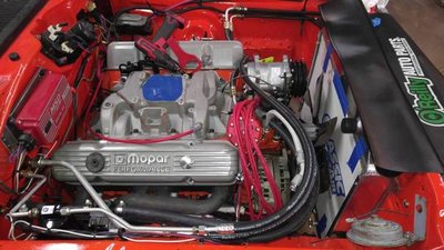
I've made a ton of progress on the car since it showed up.

Parts list:
MSD 6AL
MSD Distributor
MSD 8.5mm wires
Champion plugs
Complete Classic auto air A/C kit with a few custom touches and crimped heater hose conversion
Aluminum 4 core radiator
recovered front bucket seats
Fully sound/heat insulated floor pan and firewall
Yearone dash harness
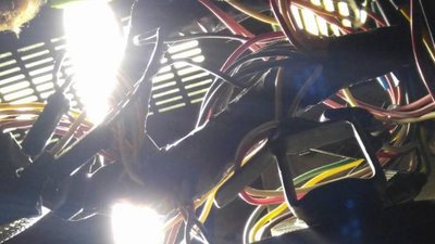
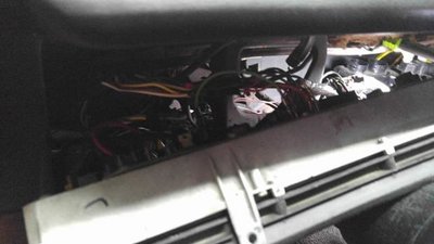
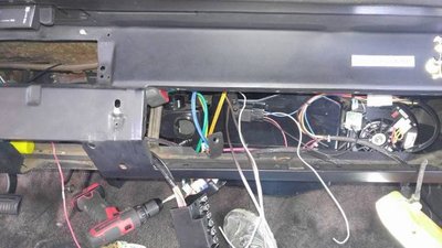
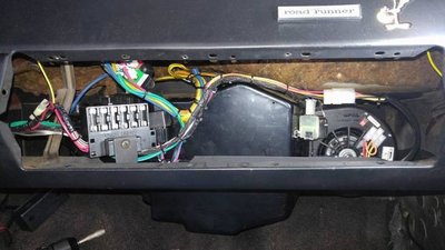
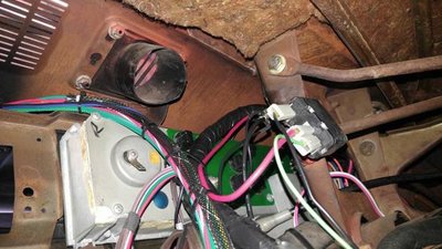
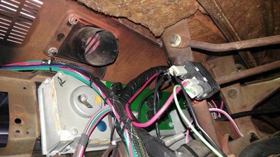
Upgraded/removed the engine bay wiring-relocated the horn relay under the dash
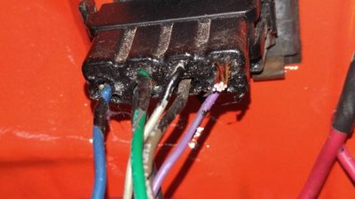
Wired MSD directly into bulkhead with factory style crimped terminals
New package tray with jute mat
new front/rear seat belts
Painted the engine bay
Removed the rusted driver side frame section under the brake line welding a new section
Removed as much of the hen housed "repairs" as we could find without putting her on a rotisserie

I'll post as many pictures as I can, the car is almost finished at this point. We just lack a few final systems checks and test runs before giving it back to the customer. I'll post them when they finally up load to the computer
 
Joined
Feb 19, 2016
Messages
22
Reaction score
0
Location
Texas
Yeah we should have her finished up today. Had found a hidden blown out exhaust thread we needed to address. So as soon as the gasket gets here we'll get her tested and tuned, then she's off for a good easy life of carting around and old man and his wife! Nice and easy with a slight chance of an occasional RAGING BURNOUT!!
 
Joined
Feb 19, 2016
Messages
22
Reaction score
0
Location
Texas
They kind of looked like either they removed rusted out panels or perhaps they were exploratory to see behind the cowl, I really don't know and couldn't tell you.
 
Back
Top