• When you click on links to various merchants on this site and make a purchase, this can result in this site earning a commission. Affiliate programs and affiliations include, but are not limited to, the eBay Partner Network.

Electronic Ign.

Roadcuda

Well-Known Member
Joined
Sep 10, 2008
Messages
10,540
Reaction score
286
Location
Rocky Hill, Ct
abodybill said:
If I go with the pertronix II does it make any difference if I use a dizzy from an automatic single point or 4 speed with dual points?

Reason I ask is I can't find my oringinal dizzy 4 speed but buddy gave me 4 single point dizzys and I don't need to buy another one.
My dizzy was a single point, so IIRC when I did mine the Pertronix unit uses the same screw holes as the points and condenser did originally. So I don't know if they will mount to a duel point dizzy.
 

abodybill

Senior Citizen Member
Joined
Jul 25, 2010
Messages
1,610
Reaction score
4
Location
MI. Farm
I got my Pertronix II today.

In the directions it has two ways of installing it:

With the ballast and Without ballast so which way is the best??
 

Roadcuda

Well-Known Member
Joined
Sep 10, 2008
Messages
10,540
Reaction score
286
Location
Rocky Hill, Ct
abodybill said:
I got my Pertronix II today.

In the directions it has two ways of installing it:

With the ballast and Without ballast so which way is the best??
I don't know if it's the best way to do it, but I installed mine with the ballast, and have had no problems so far.
 

69hemibeep

Sponge Bob Square Wheels
Joined
Sep 10, 2008
Messages
22,148
Reaction score
2,358
Location
AZ Desert,
How much voltage do they say to feed it? The one without a ballast may be using resistance wire for voltage drop. I'm afraid its time to break guy code and read the instructions or call tech :lol:
 

A31PKG

Well-Known Member
Joined
Apr 28, 2010
Messages
880
Reaction score
6
Location
Mid-Atlantic
Bill, The unit needs full 12v. The ballast stays in tact, and in the sytem as designed. They suggest splicing into the blue IGN/feed wire going to the ballast.
 

abodybill

Senior Citizen Member
Joined
Jul 25, 2010
Messages
1,610
Reaction score
4
Location
MI. Farm
69hemibeep said:
How much voltage do they say to feed it? The one without a ballast may be using resistance wire for voltage drop. I'm afraid its time to break guy code and read the instructions or call tech :lol:

All the voltage it can handle Remember this is a GREEN car :acme:

I did break the guy code and read the instructions hence my posting :lol: :lol: :lol:
 

abodybill

Senior Citizen Member
Joined
Jul 25, 2010
Messages
1,610
Reaction score
4
Location
MI. Farm
A31PKG said:
Bill, The unit needs full 12v. The ballast stays in tact, and in the sytem as designed. They suggest splicing into the blue IGN/feed wire going to the ballast.

Craig,
I kinda thought that's what I should do but wanted to check as this system is new to me as I have always had the Mopar ecu system.

That was the #2 way of hooking it up in the instructions. :thumbsup:
 

abodybill

Senior Citizen Member
Joined
Jul 25, 2010
Messages
1,610
Reaction score
4
Location
MI. Farm
Roadcuda said:
abodybill said:
I got my Pertronix II today.

In the directions it has two ways of installing it:

With the ballast and Without ballast so which way is the best??
I don't know if it's the best way to do it, but I installed mine with the ballast, and have had no problems so far.

:yesnod: :thumbsup:
 

A31PKG

Well-Known Member
Joined
Apr 28, 2010
Messages
880
Reaction score
6
Location
Mid-Atlantic
abodybill said:
A31PKG said:
Bill, The unit needs full 12v. The ballast stays in tact, and in the sytem as designed. They suggest splicing into the blue IGN/feed wire going to the ballast.

Craig,
I kinda thought that's what I should do but wanted to check as this system is new to me as I have always had the Mopar ecu system.

That was the #2 way of hooking it up in the instructions. :thumbsup:

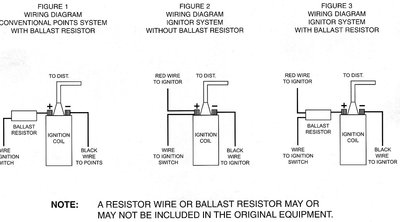
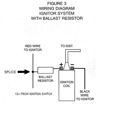
Not sure which instruction sheet you have, but this one is about a year old. The end (or #3) schematic applies to us. It's a bit unclear, as they depict two wires going into the feed side of the ballast. I made a revised version that more clearly shows the hot Pertronix wire "borrowing" system voltage from the source side of the ballast in the form of a splice. I've included pics of the original schematic and my revision of #3 below (the "corrected" one is on top).... Hope this helps!

EDIT: I just realized that you have the Pertronix II unit. The schematic shown below is for their basic unit. Not sure if there is a difference? Post a scan or pic of your instruction schematic if it's different, I'd like to see it.

Pertronix - Copy.jpg

revised.png
 

69hemibeep

Sponge Bob Square Wheels
Joined
Sep 10, 2008
Messages
22,148
Reaction score
2,358
Location
AZ Desert,
abodybill said:
69hemibeep said:
How much voltage do they say to feed it? The one without a ballast may be using resistance wire for voltage drop. I'm afraid its time to break guy code and read the instructions or call tech :lol:

All the voltage it can handle Remember this is a GREEN car :acme:

I did break the guy code and read the instructions hence my posting :lol: :lol: :lol:
Green cars are electric :acme:
 

moparstuart

Well-Known Member
Joined
Feb 27, 2009
Messages
6,627
Reaction score
7
Location
overland park ks / odessa missouri
69hemibeep said:
abodybill said:
69hemibeep said:
How much voltage do they say to feed it? The one without a ballast may be using resistance wire for voltage drop. I'm afraid its time to break guy code and read the instructions or call tech :lol:

All the voltage it can handle Remember this is a GREEN car :acme:

I did break the guy code and read the instructions hence my posting :lol: :lol: :lol:
Green cars are electric :acme:
Mine is , I plug it in every night :jester: :jester: :jester:
 

abodybill

Senior Citizen Member
Joined
Jul 25, 2010
Messages
1,610
Reaction score
4
Location
MI. Farm
A31PKG said:
abodybill said:
A31PKG said:
Bill, The unit needs full 12v. The ballast stays in tact, and in the sytem as designed. They suggest splicing into the blue IGN/feed wire going to the ballast.

Craig,
I kinda thought that's what I should do but wanted to check as this system is new to me as I have always had the Mopar ecu system.

That was the #2 way of hooking it up in the instructions. :thumbsup:

Not sure which instruction sheet you have, but this one is about a year old. The end (or #3) schematic applies to us. It's a bit unclear, as they depict two wires going into the feed side of the ballast. I made a revised version that more clearly shows the hot Pertronix wire "borrowing" system voltage from the source side of the ballast in the form of a splice. I've included pics of the original schematic and my revision of #3 below (the "corrected" one is on top).... Hope this helps!

EDIT: I just realized that you have the Pertronix II unit. The schematic shown below is for their basic unit. Not sure if there is a difference? Post a scan or pic of your instruction schematic if it's different, I'd like to see it.

Craig,
Will post a scan of the directions as soon as I can figure it out and how to do it.
 

abodybill

Senior Citizen Member
Joined
Jul 25, 2010
Messages
1,610
Reaction score
4
Location
MI. Farm
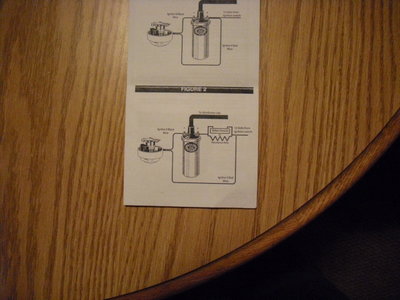
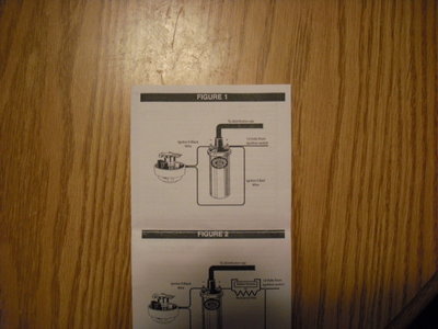
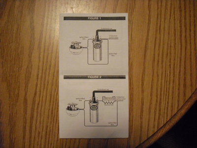
Here's pictures of the directions I got with the Pertronix II and only difference I see from Craigs post is the very first one in Craigs is the points setup.

Other then that alittle differebt where to splice the Red wire in.[attachment=2:2zeqgazj]PICT0001.JPG[/attachment:2zeqgazj][attachment=1:2zeqgazj]PICT0002.JPG[/attachment:2zeqgazj][attachment=0:2zeqgazj]PICT0003.JPG[/attachment:2zeqgazj]

If someone sees something I'm missing let me know.

PICT0001.JPG

PICT0002.JPG

PICT0003.JPG
 
Back
Top