• When you click on links to various merchants on this site and make a purchase, this can result in this site earning a commission. Affiliate programs and affiliations include, but are not limited to, the eBay Partner Network.

Pertronix ignition question

3BIRDS1X

Moderator
Staff member
Joined
Dec 8, 2008
Messages
728
Reaction score
2
Location
Mukwonago, Wi.
Pertronix ignition question:
working on installing one, they say to run the red (+) wire to the ignition switch side of the ballast resistor. researching it on the net yields some saying not to do that and to run it straight to the coil, and others say to run it to the ignition side of ballast.

Question 1 : who here is actually running one and how are you running your (+) wire? to coil or ballast?

Question 2: if going to Ballast did you splice it into your wiring harness. and if so which wire did you splice into?

Question 3: if going straight to coil should I keep my two wire connection into ignition side of ballast plugged in and unplug or ?? what to do with the coil wire on the coil side of ballast?

I'd like to not butcher up the wiring harness much, my harness has a nice blue wiring going from left side of ballast to + side of coil. the right side of ballast has a two wire connector going into it a dark blue one which appears to got to voltage regulator and a medium brown one which i believe goes to the ignition switch inside the car. which one of the two would be the better choice to splice into? or is there a better way to tie the pertronix + wire into the ballast?

Thanks all...
 

SomeCarGuy

Well-Known Member
Joined
Nov 25, 2008
Messages
1,235
Reaction score
40
Location
Sometown in KY
I ran a Petronix a few times and used that wire with no problems.

If you are running a 12 volt coil, I would bypass the ballast so it gets the full 12 volts. That would give you a place to splice and not cut the factory wires at all. I usually just get some 10 gauge wire and connect the two ballast wires and leave the ballast on the wall. Gives me more road side options in the event of a breakdown.
 

A31PKG

Well-Known Member
Joined
Apr 28, 2010
Messages
880
Reaction score
6
Location
Mid-Atlantic
I've queried two notable tech editors on the subject, Rick Ehrenberg (MOPAR Action) and Ray Bohacz (Hemmings Muscle Machines), and neither offered any real insight as to weather the ballast should or should not be used when running a Pertronix system...Neither were in a position to comment on an after-market system I suppose. Both published their responses in their columns. You may be able to search for them on their respective web-sites. Ehrenberg's was more detailed and informative, as it discussed the use of ballast resistors into the 80's when cars were all electronic anyway. Nonetheless, it wasn't exactly what I was looking for response-wise. My advise is to follow the Pertronix schematic. I currently run the wiring in my Runner as per the Pertronix schematic...powering it before the ballast. :cents:
 

Roadcuda

Well-Known Member
Joined
Sep 10, 2008
Messages
10,538
Reaction score
281
Location
Rocky Hill, Ct
I have an Ignitor II in my car. I ran the red wire right up to the BR, and was able to secure it to the same connector that was already on the BR so I didn't have to splice into the harness. So far the car has run great with no problems.
 

SomeCarGuy

Well-Known Member
Joined
Nov 25, 2008
Messages
1,235
Reaction score
40
Location
Sometown in KY
I don't understand why the magazines won't do some research and run an article about the use of a ballast.

It isn't needed when you have a 12 volt coil. Eberg claims that bypassing it will fry the ECU in short order for some reason. That isn't true and I have no idea why he seems to think so. If it were going to burn up anything, I would've walked a TON in my cars in the past. If you are running a ballast, measure the voltage at the coil and you will see how much power you are cutting off. That is a ton of potential energy lost coming out of the coil when it is all said and done.

That is with the use of USA made parts. Use China crap, and all bets are off.
 

3BIRDS1X

Moderator
Staff member
Joined
Dec 8, 2008
Messages
728
Reaction score
2
Location
Mukwonago, Wi.
The instructions do say to go thru the ballast, just that if that's the case you would think there would be better instructions on how to wire it to the ballast or a jumper lead supplied to splice into the incoming connector instead of having to rig something up, I'm not a big fan of electrical stuff to start with and I can't seem to come up with a nice way of doing it.

Plenty of people out there do run it straight to the coil but then what to do with the existing wiring going to the ballast? does that run to the coil so there are two wires going to coil? I think I would like to cleverly run it thru the ballast. I can only come up with baring the wire and putting it over the ballast prong and jaming the feed plug over the top of it which seems pretty hack-ish to me if it would even fit on. one would think for the amount of mopars out there they would have the kit a little easier and foolproof to install. they make those press together wire connectors that have a blade on it and could maybe be wedged in with the stock plug but for an ignition wire it doesn't seem like a good idea to me. I'm open for any good and detailed ideas.
 

A31PKG

Well-Known Member
Joined
Apr 28, 2010
Messages
880
Reaction score
6
Location
Mid-Atlantic
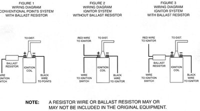
Here is a scan of the schematic. It shows the red wire attached before the ballast. According to Pertronix, they want the unit to receive a full 12 volts. I accomplished this by splicing a companion wire into the blue ballast feed wire and re-taping. It looks pretty good. I'm with you on hacking wiring harnesses, but it can be done with minimal intrusion. Lowering the voltage to the coil will not nessasarily lower its output. The kilovolts that are created in the secondary windings are a function of when the magnetic field collapses in the primary windings, and not entirely dependent on the actual input voltage. In other words, a 12v coil can still produce 40 KV with less than 12 volts. On top of that, the spark plug is only going to use what it needs, usually 10-15KV. Engineers knew this, so in an effort to prolong point life, they invented the ballast resistor to lower the current. The ballast also acts as a circuit "dampener" to smooth out voltage spikes. According to Dr. E, this lower voltage was deemed a good thing into the electronic ignition era, as it would also prolong the life of control modules - which were nothing more than simple transistor switches....the same principle used in the Pertronix unit.

Pertronix.jpg
 

3BIRDS1X

Moderator
Staff member
Joined
Dec 8, 2008
Messages
728
Reaction score
2
Location
Mukwonago, Wi.
yeah that is the drawing I got with the kit too.

"I accomplished this by splicing a companion wire into the blue ballast feed wire and re-taping"

so in simpler moron terms (that I can follow) are you saying I need to splice my red pertronix wire into the blue feed wire (which shares the same plug with the medium brown wire) and use the factory blue wire as is that runs from the ballast to the coil? or what do you mean by "companion" wire. thanks
 

A31PKG

Well-Known Member
Joined
Apr 28, 2010
Messages
880
Reaction score
6
Location
Mid-Atlantic
You want to use the SINGLE blue wire going into the ballast. This is the 12v feed from the "IGN" terminal of the voltage regulator. The double wire on the other end of the ballast contains a brown wire which is the ballast by-pass from the igniiton switch, and a blue wire that carries the reduced voltage to the coil. Don't use those! If you untape the harness, you can splice into the blue wire and run it along the harness to the front of the engine (thus the term "companion") where you can connect it to the red pertronix wire. After that, retape, and you're done! I'm not sure why they want it wired this way, it seems to me that you could use any switched 12v source. If I get a chance tomorrow, I'll try and take a pic of my set-up...
 

3BIRDS1X

Moderator
Staff member
Joined
Dec 8, 2008
Messages
728
Reaction score
2
Location
Mukwonago, Wi.
are you sure that's not goofed?? I am pretty sure the single prong on the passenger side of car is a single blue wire going straight to the coil and on the drivers side is the two prong which looks like a med. brown and dark blue going to voltage reg. and the brown to ign. switch like you say. I knew I should have taken a pic when I could have :brickwall:
regardless I just need to splice into wire coming off of voltage regulator to ballast . I just hate having stuff apart.
 

glhcarl

Well-Known Member
Joined
Sep 12, 2008
Messages
408
Reaction score
1
I have mine wired through the ballast restsistor, as shown in Figure 3 of the instructions. No problems in over six years!
 

3BIRDS1X

Moderator
Staff member
Joined
Dec 8, 2008
Messages
728
Reaction score
2
Location
Mukwonago, Wi.
never mind I looked at the wiring schematic and now it makes alot more sense now I guess having blue wires in and out of ballast kind of threw me. and I'm not home right now either so that's not helping. I might see if I can't tie it in right at or near the voltage regulator thanks much I'll post in the morning how it's going.
 

A31PKG

Well-Known Member
Joined
Apr 28, 2010
Messages
880
Reaction score
6
Location
Mid-Atlantic
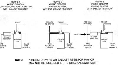
Using the "IGN" terminal of the voltage regulator as a bus for the power feed to the pertronix unit is a good idea. You will be able to conceal the wire better too. The schematic they provide is a little confusing, as they show two wires going into the ballast...In reality they should have shown the pertronix feed wire as spliced into the ballast power feed wire, thus by-passing the ballast, yet leaving it otherwise intact in the vehicle wiring. The voltage for the pertronix unit does not "pass through" the ballast, rather, it "borrows" voltage ahead of the ballast so that it (the ballast) still remains in the factory circuit.

Hope I didn't muddy the waters....... :cheers:
 

3BIRDS1X

Moderator
Staff member
Joined
Dec 8, 2008
Messages
728
Reaction score
2
Location
Mukwonago, Wi.
totally makes sense now thanks for foolproofing it for me, Petronix could have alot more clear and I just don't like to jump in and do stuff like this either.
 

Big John

Sit back, relax Don't bitch about the cigar smoke
Joined
Sep 8, 2008
Messages
5,057
Reaction score
79
FWIW, I'm going to use a Pertronix unit in my 53 Chrysler. As I understand it, it's the same unit as all the others, just a different mounting configuration. No ballast and I'm using the Pertronix coil.

I do think you may want to see what coil they recommend and match the primary resistance. The Ignitor 2 and 3 use a lower primary resistance coil. http://www.pertronix.com/catalogs/pdf/ptx/2010/ptx2010_coils.pdf
 

3BIRDS1X

Moderator
Staff member
Joined
Dec 8, 2008
Messages
728
Reaction score
2
Location
Mukwonago, Wi.
I asked about the coil when I bought it, I have the entry level ignition kit and they told me those run fine with the stock points coil so I'll give it a shot, I can always carry a coil with just in case. The wiring turned out great off an old wiring harness I sottered in a two wire plug that mates with the ballast prong one wire for the ignition switch feed and one for the pertronix "+" looks factory enough to me except I now have 2-wires on each side of ballast I doubt if anyone will ever question it. alot going on so I won't have a chance to fire it up until end of the week if I'm lucky. Thanks :cheers:
 

Roadcuda

Well-Known Member
Joined
Sep 10, 2008
Messages
10,538
Reaction score
281
Location
Rocky Hill, Ct
3BIRDS1X said:
I asked about the coil when I bought it, I have the entry level ignition kit and they told me those run fine with the stock points coil so I'll give it a shot, I can always carry a coil with just in case. The wiring turned out great off an old wiring harness I sottered in a two wire plug that mates with the ballast prong one wire for the ignition switch feed and one for the pertronix "+" looks factory enough to me except I now have 2-wires on each side of ballast I doubt if anyone will ever question it. alot going on so I won't have a chance to fire it up until end of the week if I'm lucky. Thanks :cheers:
I also have two wires on each side of the BR and like you say, most people won't know the difference. And I am using a stock coil with the Ignitor II on 2 cars and have had no problems so far!
 

newbaufish

Member
Joined
Jun 28, 2011
Messages
10
Reaction score
0
Location
Seattle WA Area
I just went through the installation of the Pertronix III on my system, there are clear instructions that indicate this version of the Pertronix needs to have full charge and NOT be routed through the Ballast Resistor so the answer is "depends on the Pertronix Unit". I have made a jumper that hides behind the resistor unit and looks just fine. Was a lot more involved saga than that, but I'll take care of that in another forum post on another day.
 

A31PKG

Well-Known Member
Joined
Apr 28, 2010
Messages
880
Reaction score
6
Location
Mid-Atlantic
newbaufish said:
I just went through the installation of the Pertronix III on my system, there are clear instructions that indicate this version of the Pertronix needs to have full charge and NOT be routed through the Ballast Resistor so the answer is "depends on the Pertronix Unit". I have made a jumper that hides behind the resistor unit and looks just fine. Was a lot more involved saga than that, but I'll take care of that in another forum post on another day.

To my knowledge, none of their control units are to be run through the ballast resistor. They all must have full system voltage (12v). The Pertronix diagram merely shows the connection occurring on the 12v feed wire going to the ballast, but not through it...any switched 12v source would work. By-passing the ballast with a jumper wire allows you to use the existing blue (+) lead to the coil to provide a power source, but it excludes the resistor from the circuit. Although this is probably not a big deal, it could cause the coil to overheat over time. I would keep the resistor in the circuit, and just power the ignitor unit either at the feed wire to the BR or at the "IGN" bus at the voltage regulator. Does your schematic look like the one I posted? I'd be curious to see it. Here's my version of how the schematic should look for clarity purposes. Obviously, there are other ways to get the 12v feed without cutting the wire... I think it should look more like this...see the last diagram:

corrected.jpg
 

3BIRDS1X

Moderator
Staff member
Joined
Dec 8, 2008
Messages
728
Reaction score
2
Location
Mukwonago, Wi.
as I looked into this on the net it is amazing how many different opinions and theories there are on how to instal these, and how good they are , what coils to use etc. if you ask me they could be a little more clear on some of it.
 
Back
Top